
Begin with rooms, people, and outcomes
Cable counts make sense only after the household has described what each space should do. A television wall may need network, control, audio, signal, power, backing, and a path to remote equipment; a home office may need dependable wired data and resilient Wi-Fi; a patio may need weather-rated connectivity, audio, shading, and camera coverage. Room names alone are not enough because two bedrooms can have very different uses.
Build the schedule around confirmed furniture, display, desk, bed, window, door, and cabinet locations whenever possible. Mark current requirements separately from future options so the construction team knows what must be terminated now and what may be left as a labeled spare or pathway. The planner assumes preliminary locations; changes to cabinetry, reflected ceiling plans, millwork, equipment selections, or interior design should trigger a coordination review.
- Record the intended experience and device location for every room.
- Identify which systems must keep working during an internet outage.
- Coordinate camera views, shade pockets, speaker positions, and control locations with architecture and interiors.
- Separate confirmed scope, allowances, and future-only provisions.
Treat the rack and service spaces as building infrastructure
Home-run cabling usually returns to a central rack or structured-wiring location, making that space a major early decision. It needs a practical path from the service-provider entry, enough wall or rack area for terminations and equipment, dedicated electrical coordination, grounding and bonding where applicable, ventilation or cooling based on the final heat load, lighting, and room to service connections without dismantling the installation.
A convenient framing cavity can still be a poor equipment location if it is hot, dusty, wet, inaccessible, too shallow, or expected to hold unrelated storage. Garages and exterior-adjacent spaces in Arizona can expose electronics to severe temperatures, so equipment ratings and a heat-load plan matter. The rack layout should reserve bend radius, cable management, patching space, power distribution, network hardware, control equipment, and documented spare capacity rather than filling every usable unit on day one.
- Confirm service-provider entry and demarcation route.
- Calculate electrical load, Power over Ethernet budget, battery-backup scope, and heat output from selected equipment.
- Keep working clearances and service access free of shelves and household storage.
- Label every home run at both ends and match it to the room schedule.
Coordinate television, audio, and control runs as assemblies
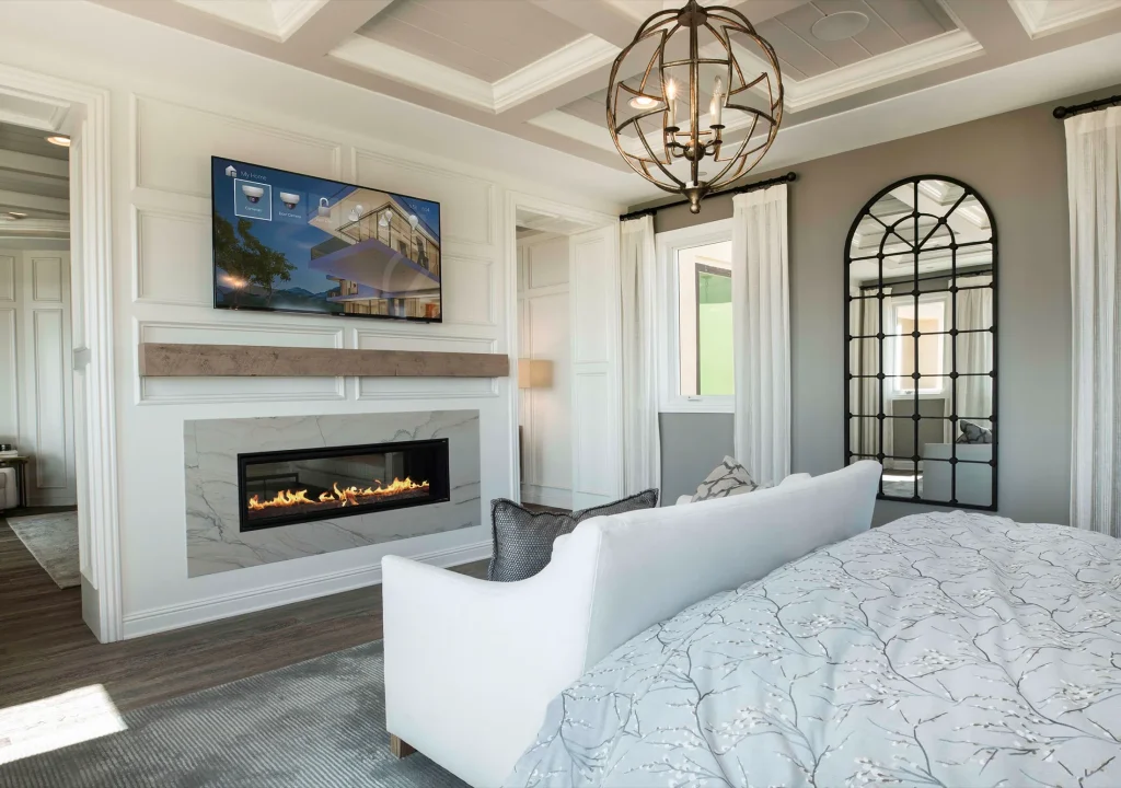
A clean television location is more than a signal cable. Confirm the display size and mount concept, framing or listed backing, receptacle position, low-voltage entry, soundbar location, local versus remote source equipment, control method, and a replaceable route for connection types that may change. If equipment is centralized, its signal path and control strategy must be selected as a system; an arbitrary long cable placed before product selection can become the weak link.
Speaker rough-in requires the same discipline. Ceiling and wall speaker positions should follow the listening layout, lighting plan, structure, HVAC, sprinklers, acoustic goals, and the requirements of the selected speaker. Avoid placing every round ceiling device on a decorative grid before confirming performance. Document cable destination, polarity, service loop, bracket or back-box requirements, and any fire or acoustic assembly that the penetration affects.
Plan network, security, shades, and controls before their locations disappear
Wired network outlets support stationary devices and free Wi-Fi capacity for mobile devices. Candidate Wi-Fi access-point locations should be distributed around the floor plan and home-run to the network rack; the final count and exact locations still require network design. Cameras, door stations, gates, touchscreens, and other Power over Ethernet devices need both data-path and power-budget planning, while life-safety and monitored security systems may have separate provider and code requirements.
Motorized shades and drapery depend on the chosen architecture: power supply, wire type, conductor count, control topology, pocket construction, and service access can differ by manufacturer and model. Lighting control can also alter switch-leg, neutral, keypad, panel, and enclosure requirements. These systems should never be reduced to a generic 'smart wire.' Obtain the current rough-in documents for the products being specified and reconcile them with window schedules, elevations, millwork, and electrical drawings.
- Place network drops where equipment will live, not wherever a wall is easiest to reach.
- Review camera purpose and field of view before fixing junction locations.
- Confirm shade-pocket depth, power-feed side, wire route, and accessible service point.
- Keep security, fire-alarm, electrical, and low-voltage responsibilities explicit.
Use pathways, blocking, and spare capacity deliberately
Future readiness is strongest where a pathway can reach a likely change point. Conduit or innerduct can be valuable between an accessible equipment location and television walls, attic or crawl spaces, exterior service points, specialty rooms, and other hard-to-reach areas. A conduit is not useful merely because it exists: its route, diameter, bends, fill, pull points, firestopping, end treatment, and accessibility determine whether a future cable can actually be installed.
Blocking is equally time-sensitive. Displays, speakers, projectors, shades, cameras, access points, touchscreens, racks, and specialty equipment may need structure in exact locations. Photograph every wall with a visible tape measure or other dimension reference before insulation and drywall, and preserve marked plans showing pathways and cable IDs. Spare cables should be appropriate for the environment, supported and protected, labeled at both ends, and terminated or safely secured according to the approved design.
- Avoid unserviceable bends and conduits that terminate behind fixed finishes.
- Provide pull strings only as part of a pathway plan that protects them during construction.
- Coordinate penetrations through rated, exterior, acoustic, waterproofed, and insulated assemblies.
- Record dimensions from permanent framing references, not temporary materials.
Complete a pre-drywall validation walk
The final open-wall walk is the moment to compare the room schedule with conditions in the field. Trace each cable from origin to destination; confirm labels, support, separation, terminations, accessible pathways, backing, box locations, and service loops; and check for damage caused by other trades. Reconcile the installation with the latest architectural, electrical, lighting, reflected-ceiling, millwork, shade, security, and technology plans rather than relying on an earlier markup.
Code and professional verification are required wherever the plan touches line-voltage power, grounding or bonding, fire-resistance-rated assemblies, penetrations, environmental spaces, hazardous locations, structural attachments, or manufacturer-specific safety requirements. The authority having jurisdiction and project professionals determine what is acceptable. Only after deficiencies are corrected should the team capture dated photographs, test results, cable schedules, rack elevations, product rough-in sheets, and an as-built set for the homeowner.
- Verify every planned location against actual furniture, cabinetry, doors, windows, and equipment.
- Test and document installed cabling with methods appropriate to its type and intended application.
- Close coordination issues before insulation and drywall conceal the work.
- Store the final schedule, photos, reports, and as-built drawings together.
Sources + limitations
What supports this Guide.
- TIA: ANSI/TIA-570-E Residential Telecommunications Infrastructure Standard
- TIA: TR-42 Telecommunications Cabling Systems
- CEDIA: The Ultimate Smart Home Wiring Guide
- NFPA 70: National Electrical Code Development
Planning boundary
This planner organizes technology decisions; it does not determine code compliance or replace construction documents. Have the responsible integrator, electrician, builder, design team, product manufacturers, and authority having jurisdiction verify the final pathways, cable types, penetrations, firestopping, electrical work, support, separation, and testing before surfaces are closed.