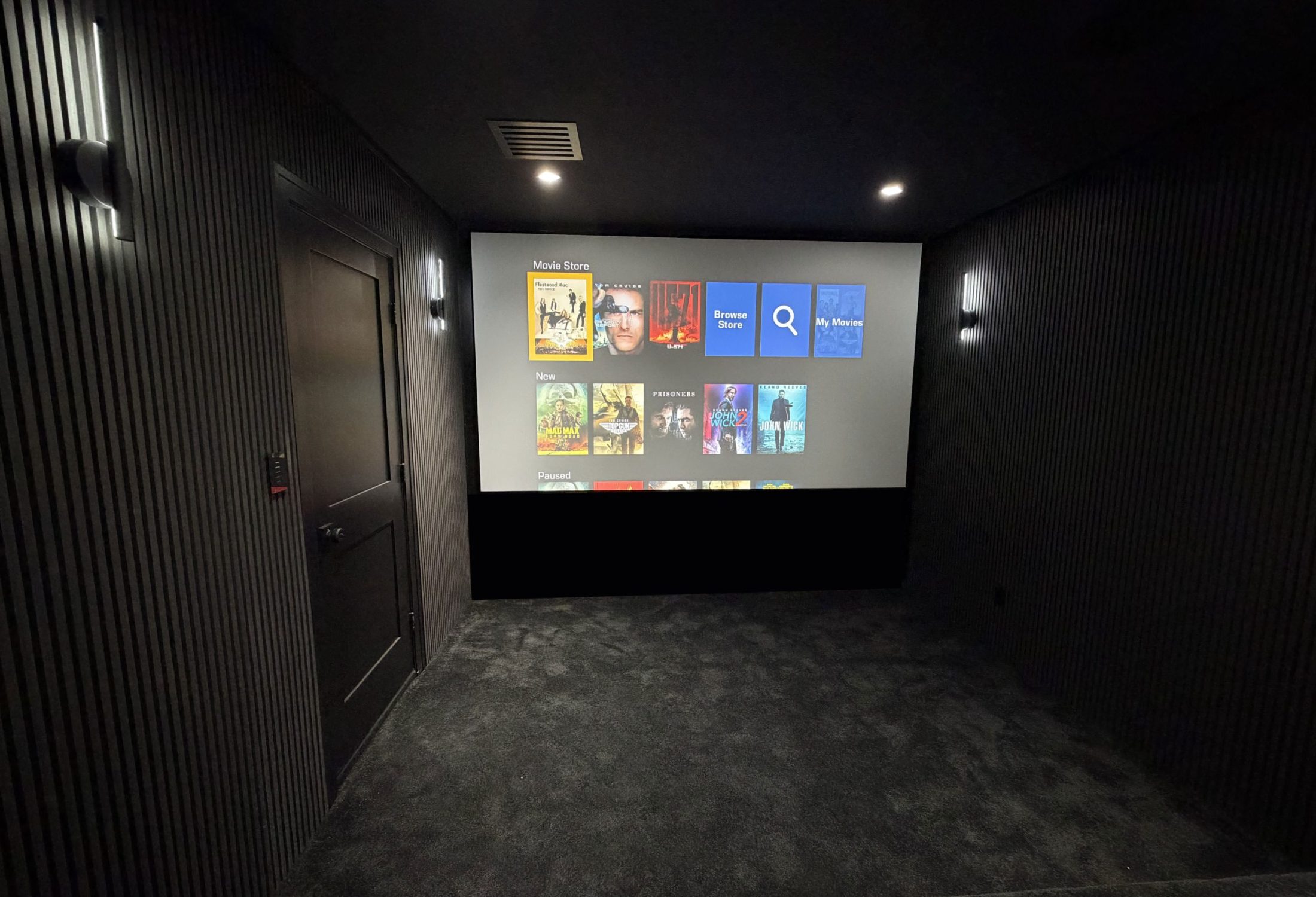
A well-designed surround sound system is a coordinated room, not a box count. Speakers, subwoofers, processor or receiver, amplification, wiring, seating, finishes, and calibration all influence what reaches the listener. A modest 5.1 system placed around a clear reference seat can sound more coherent than a larger system forced into locations chosen after the architecture is finished.
That is why the planning process differs between a dedicated cinema, a family media room, an open great room, and a retrofit in a finished Arizona home. Each can support compelling sound, but not through the same layout. The job is to preserve the soundtrack’s intended direction and scale while respecting doors, windows, vaulted ceilings, walkways, seating, cabinetry, reflective surfaces, and the level of visible technology the room can accept.
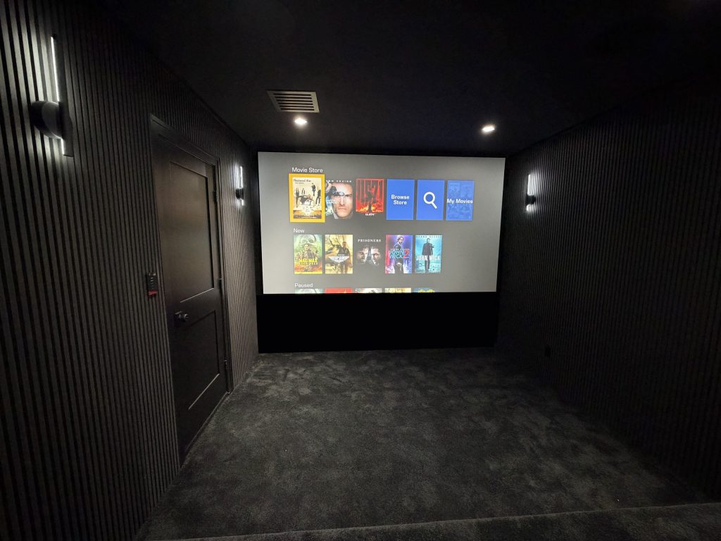
How surround sound works
Stereo uses left and right channels to create a soundstage in front of the listener. Surround sound expands that stage by assigning audio to additional channels around the listening area. In a conventional home-theater layout:
- Left and right front channels carry much of the music, movement, and width across the screen.
- The center channel anchors dialogue and on-screen action so voices remain connected to the image across more than one seat.
- Surround channels carry side and rear information, ambience, and directional effects.
- Height channels in an immersive format add a vertical layer above the listener.
- The LFE channel carries a dedicated low-frequency effects signal. The system may also redirect bass from speakers that cannot reproduce the lowest frequencies to one or more subwoofers through bass management.
The content source, playback device, HDMI path, receiver or processor, amplifier channels, and speaker configuration must all support the desired format. A Dolby Atmos logo does not make every program native Atmos, and a soundbar that virtualizes channels is not physically identical to a room with discrete ear-level and overhead speakers. Both may be useful in the right setting; they should simply be described honestly.
5.1, 7.1, 5.1.4 and 7.1.4 surround sound decoded
Dolby’s technical explanation of x.y.z speaker notation is more precise than the shorthand often used in product marketing:
- x = the number of ear-level channels.
- y = the number of dedicated LFE channels. In common home layouts this is “.1,” even when more than one physical subwoofer reproduces that signal.
- z = the number of overhead or height channels in an immersive layout.
| Layout | What it contains | Where it often fits | Primary design question |
|---|---|---|---|
| 5.1 surround sound | Left, center, right, one surround pair, and one LFE channel. | Media rooms, modest dedicated rooms, and spaces with one primary seating area. | Can the surrounds sit to the sides and slightly behind the listeners without being pushed into the rear corners? |
| 7.1 surround sound | Left, center, right, side surrounds, rear surrounds, and one LFE channel. | Rooms with meaningful space behind the seating and enough width for separate side coverage. | Can side and rear channels occupy distinct positions, or will they collapse into nearly the same location? |
| 5.1.4 Dolby Atmos | A 5.1 ear-level layer plus four height channels. | Rooms where vertical immersion matters more than adding rear surrounds, including some shorter rooms. | Can four height speakers form front and rear overhead zones around the reference seating area? |
| 7.1.4 Dolby Atmos | A 7.1 ear-level layer plus four height channels. | Larger dedicated theaters with sufficient width, depth, processing, amplification, and speaker coverage. | Can every bed-layer and height channel remain spatially distinct across the intended seats? |
More channels can improve spatial continuity, but only when they are useful. If a sofa is against the rear wall, the room may not support convincing rear surrounds. If a sloped, vaulted, or absorptive ceiling prevents a predictable reflection, upward-firing Atmos modules may be a poor default. If multiple seating rows span a large area, a layout designed for a single center seat may need different speaker coverage and subwoofer strategy.
Speaker placement begins with the listening area
Start with the main listening position or listening area, not the walls. Dolby’s consumer speaker setup guides express placement as angles around the listener for a reason: two rooms with the same dimensions can require different coordinates when their screens and seats move.
For a conventional 5.1 layout, the front left and right speakers create a stable stage around the image, the center sits on the screen axis, and the surround pair sits to the sides and somewhat behind the listening position. The subwoofer shown below is only a starting point; low-frequency placement should be tested in the actual room.
- Ear-level speaker
- Subwoofer starting point
- Reference seat
Front speakers and the screen should be designed together
The center channel carries much of the dialogue, so its acoustic position should feel connected to the image. A dedicated cinema may use an acoustically transparent screen with the front speakers behind it. A media room may place the center above or below a television. Either arrangement requires attention to the speaker’s radiation pattern, mounting, cabinetry, reflections, and sightlines. Hiding a speaker inside an unplanned cabinet opening can change its sound and restrict coverage.
Surround speakers are not simply “back speakers”
In 5.1, the surround pair belongs beside and somewhat behind the listening position. In 7.1, side surrounds and rear surrounds are separate channels. That difference is essential: adding rear channels only helps when the room gives them distinct geometry. Dolby’s downloadable 5.1 and 7.1 placement diagrams provide useful starting angles, but they are not fixed-foot blueprints for every room.
Dolby Atmos and the height layer
Dolby Atmos can render sound objects in three dimensions rather than confining every element to a fixed horizontal channel. In a discrete home-theater layout, the height layer is typically created by in-ceiling or on-ceiling speakers. Dolby Atmos-enabled modules can also direct sound toward a suitable ceiling so a reflected path reaches the listener.
Dolby’s home-theater installation guidance recommends four height speakers for the most precise movement and identifies important ceiling conditions for upward-firing modules. A flat, rigid, reflective ceiling is a different acoustic surface from a steeply vaulted, irregular, or heavily absorptive one. The correct choice depends on the actual ceiling and seating—not just the desire to avoid cutting drywall.
- Ear-level speaker
- Height speaker
- Subwoofer starting point
A 5.1.4 layout is not automatically inferior to 7.1.4. In a shorter room, preserving four useful height channels while using one surround pair may create a more coherent result than forcing rear surrounds against the listeners. In a larger dedicated room with space behind multiple seating rows, 7.1.4 can provide smoother horizontal movement and better rear coverage. The specialized Camelback Smart Homes page on Dolby Atmos design and installation in Phoenix owns the deeper service intent.
Subwoofers: LFE, bass management, placement and calibration
The subwoofer section is where channel notation is most often misunderstood. In “5.1” or “7.1.4,” the middle digit describes the LFE channel. The physical subwoofer system may use one cabinet or several. It may reproduce both the LFE channel and low-frequency content redirected from other speakers through bass management.
Bass behaves differently from midrange and treble because room dimensions create strong standing-wave patterns. A seat can experience a large peak at one frequency and a deep cancellation at another; moving the seat or subwoofer can change the result dramatically. That is why “put the sub in the corner” is not a universal design method.
Multiple subwoofers are valuable when they are positioned and calibrated as a system. The goal is often more consistent bass across a listening area, not simply higher output. Research summarized in Harman’s official paper “Subwoofers: Optimum Number and Locations” shows that strategically placed multiple subwoofers can reduce seat-to-seat variation in modeled rectangular rooms. The CEDIA/CTA-RP22 Immersive Audio Design Recommended Practice also treats room volume, proportions, seats, subwoofer quantity and location, absorption, and electro-acoustic optimization as one low-frequency design problem.
A useful subwoofer design sequence
- Define the listening area. One reference seat and three rows of seating are different optimization problems.
- Model or test candidate locations. Construction plans can narrow options; in finished rooms, measurements reveal the real response.
- Choose adequate output and bandwidth. The system needs clean capability for the room and target performance, not just a large driver diameter.
- Set bass management deliberately. Crossover choices depend on the actual loudspeakers, subwoofers, room, and processor—not one internet default.
- Align level, delay, phase, and polarity. The subs must work with one another and sum correctly with the main channels.
- Measure more than one seat. A single perfect graph at the center can hide severe variation elsewhere.
Wired vs. wireless surround sound
“Wireless home theater” is an imprecise label. It can mean wireless audio between a soundbar and rear speakers, a proprietary radio link to active speakers, Wi-Fi streaming to networked products, or a wireless adapter feeding an amplifier. None of those descriptions automatically answers how each device receives power, how channels stay synchronized, what happens during interference, or whether products from different brands are compatible.
| Approach | What the room still needs | Strengths | Tradeoffs to verify |
|---|---|---|---|
| Passive wired speakers | Speaker cable from amplifier to each speaker; conduit or access path where practical. | Predictable channel path, broad equipment choice, no AC outlet at each passive speaker, and strong new-build longevity. | Cable routes, termination, service loops, fire-blocking, future access, amplifier location, and drywall coordination. |
| Active wireless speakers | Usually AC power at each speaker plus a compatible transmitter, radio or network path. | Useful in some finished rooms where signal cabling is difficult and a supported ecosystem fits the objective. | Power visibility, interference, latency/synchronization, proprietary compatibility, software support, and recovery after outages. |
| Soundbar with wireless surrounds | Power and placement for the bar, surrounds, and often a wireless subwoofer. | Lower visual and construction impact; practical for multipurpose rooms. | Less placement freedom, ecosystem limits, room coverage, upgrade path, and difference between virtualized and discrete channels. |
| Hybrid retrofit | A deliberate mix of existing cable, new low-voltage paths, localized amplification, and supported wireless links. | Can preserve finishes while improving placement and serviceability. | More integration testing; every wired and wireless dependency must be documented. |
CEDIA’s current smart-home wiring guide recommends planning speaker cable and home runs before drywall. That advice is less about rejecting wireless products than preserving options. Low-voltage cable and conduit are inexpensive to coordinate during construction compared with opening a finished ceiling later. They also let future owners change speakers, amplification, or formats without relying on one discontinued radio ecosystem.
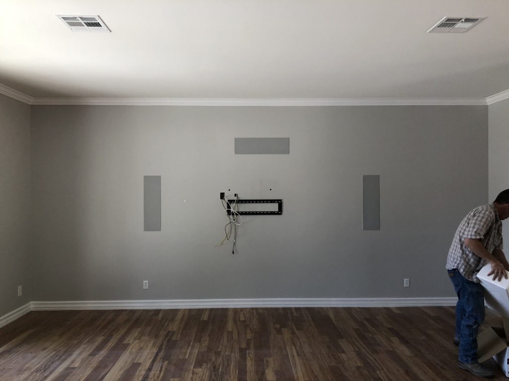
In a retrofit, a qualified integrator can evaluate attics, crawl spaces, millwork, baseboards, closets, and repairable access points before declaring that every rear speaker must be wireless. Camelback Smart Homes can also coordinate low-voltage work with drywall repair where the route requires a controlled opening. Do not run line-voltage power or bury unsupported extension cords as a workaround for “wireless” speakers.
Room correction, acoustic treatment and soundproofing are different tools
These three terms are often bundled together even though they solve different problems:
- Acoustic treatment controls reflections, decay, and low-frequency behavior inside the room through absorption, diffusion, bass treatment, geometry, furnishings, and placement.
- Sound isolation or soundproofing reduces sound transfer into or out of the room through construction assemblies, seals, mass, decoupling, doors, penetrations, and mechanical-system design.
- Room correction uses measurements and digital signal processing to adjust parameters such as level, delay, equalization, and—in compatible systems—subwoofer integration or bass control.
Electronic correction is not a substitute for physical design. It cannot move a surround speaker away from a doorway, create space behind a sofa, stop a rattling register, change a glass wall into a controlled reflection, or fill every deep cancellation without consequences. It is most effective after the room, seats, speakers, and subwoofers are placed as intelligently as practical.
Acoustic treatment should also be designed rather than applied by recipe. Covering every surface with absorption can remove useful energy and produce an unnaturally dead room. Reflections may be controlled differently at the front wall, side walls, rear wall, ceiling, and low frequencies. With upward-firing Atmos modules, the desired ceiling reflection is part of the playback method; indiscriminate ceiling absorption can undermine it. For a deeper companion discussion, see the Camelback Smart Homes article on home-theater soundproofing.
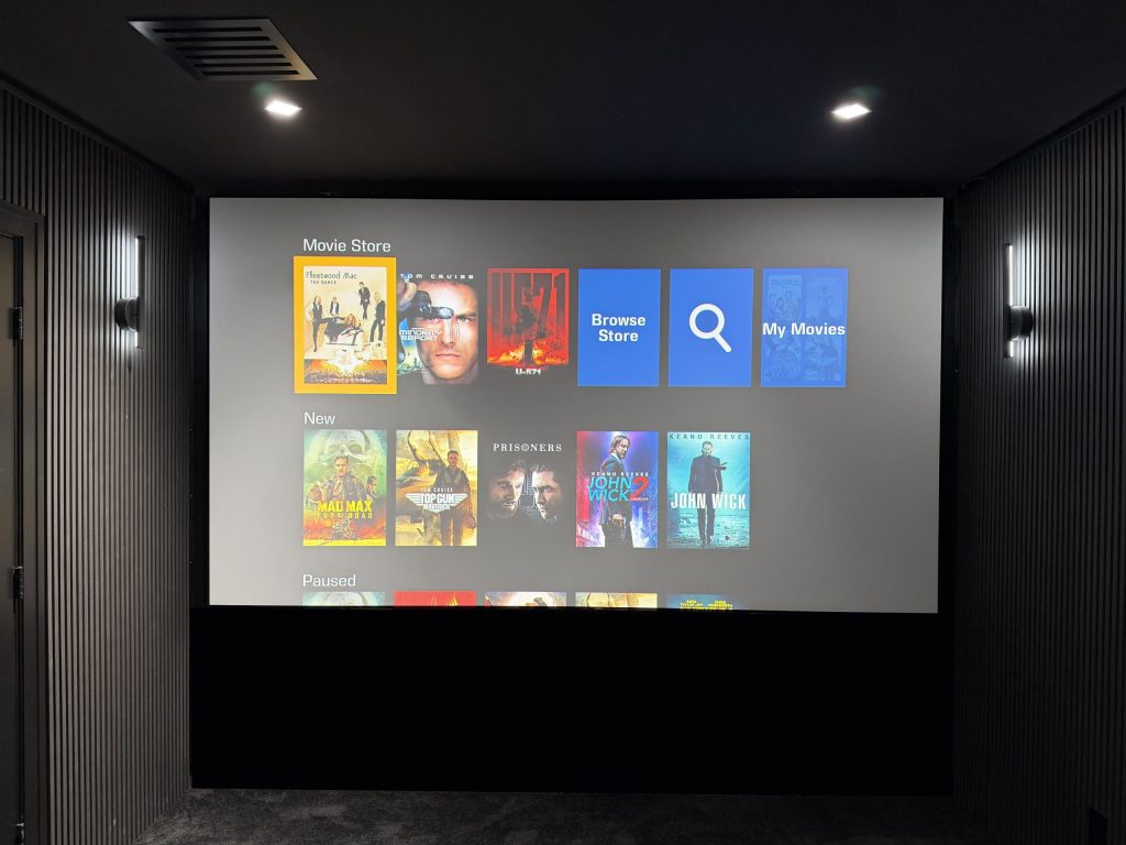
What professional surround sound calibration actually changes
Calibration begins after installation checks confirm polarity, channel identity, speaker health, safe amplifier operation, and signal routing. A trained calibrator then measures the system using the microphone, software, and procedure appropriate to the processor or receiver. The work may include:
- Verifying that every channel maps to the correct physical speaker.
- Setting reference distances or measured delays so arrivals align at the listening area.
- Balancing channel levels and confirming available headroom.
- Choosing crossovers and bass-management routing based on measured speaker and subwoofer behavior.
- Aligning multiple subwoofers and their transition to the main channels.
- Measuring several positions rather than optimizing one microphone point in isolation.
- Applying room-correction filters within a sensible range after physical issues are addressed.
- Saving documented profiles and validating familiar film, music, and test material.
Dolby describes calibration as optimizing room configuration and speaker placement, then adjusting level, equalization, and delay toward a defined measured target. Platforms differ, so their microphone pattern and workflow should not be mixed. For example, Anthem’s current ARC Genesis guide requires several distributed microphone positions, while Dirac Live measures how the room and speaker system interact and can add compatible bass-control functions. Camelback Smart Homes also supports high-performance processing and calibration through its StormAudio solutions.
How the plan changes by Arizona room type
Dedicated theater
Best opportunity to coordinate screen axis, seating rows, speaker coverage, subwoofer locations, treatment, isolation, lighting, equipment ventilation, and service access. Channel count should follow the performance target and coverage area, not prestige.
Multipurpose media room
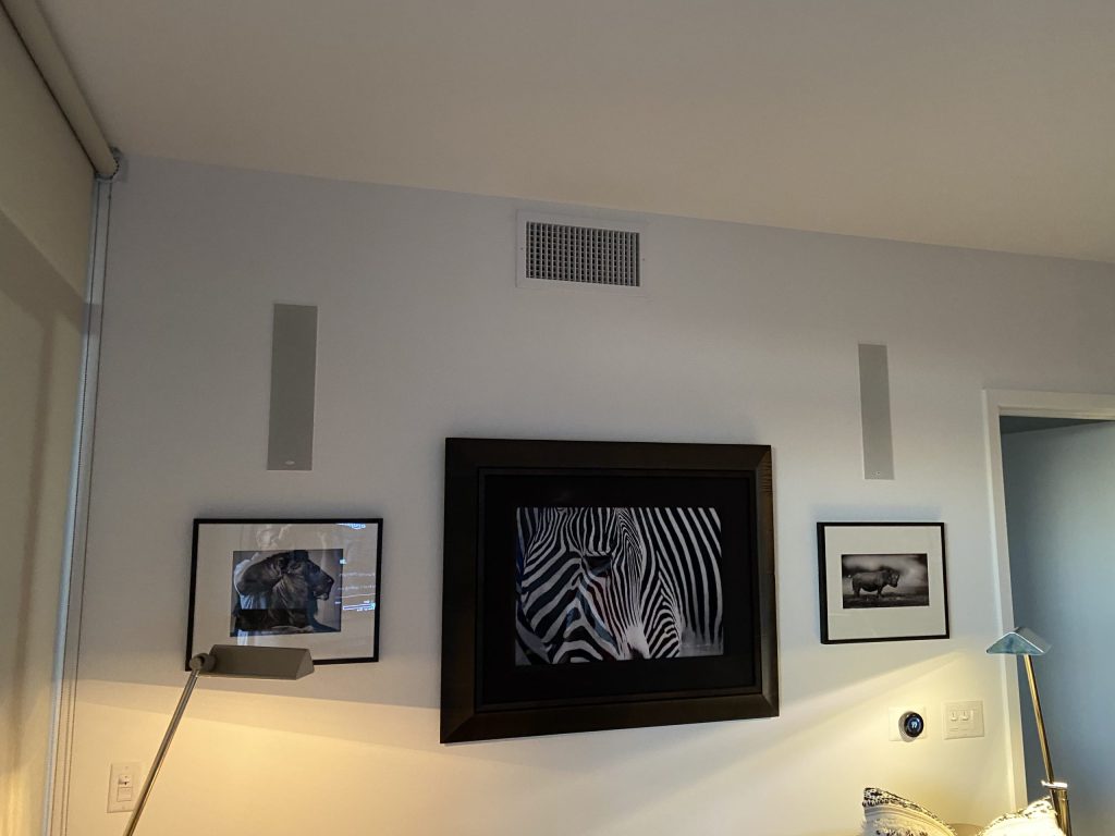
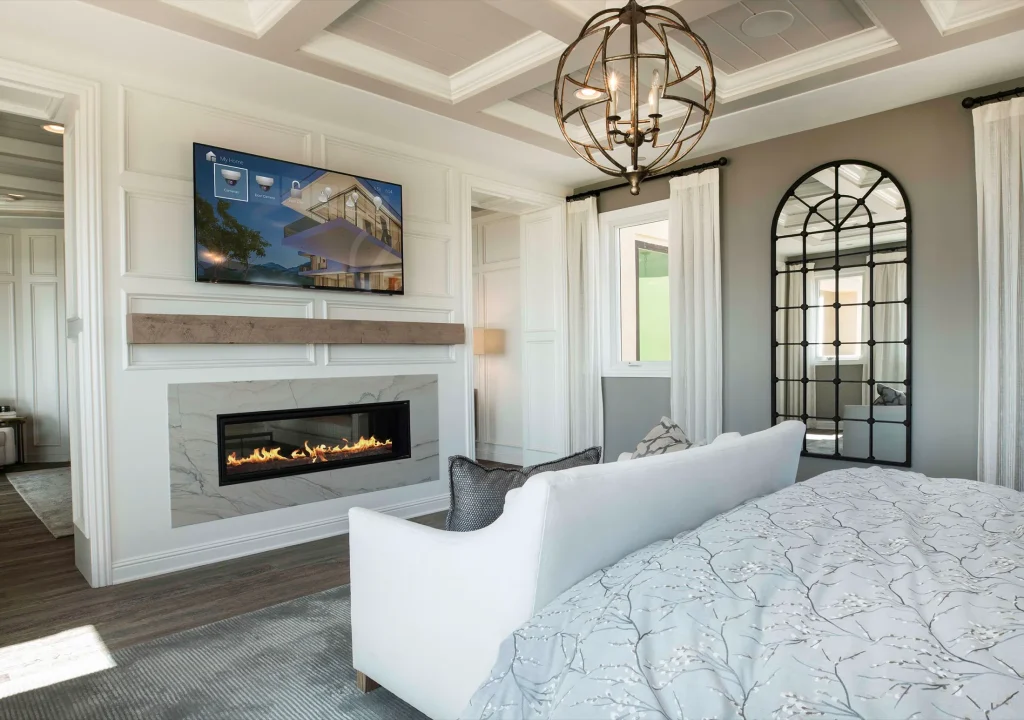
Doors, windows, cabinetry, conversation seating, and daylight may limit symmetry. A carefully placed 5.1 or 5.1.4 system can be more useful than a compromised larger layout. Architectural or invisible speakers may reduce visual impact when their acoustic tradeoffs are designed intentionally.
Open great room
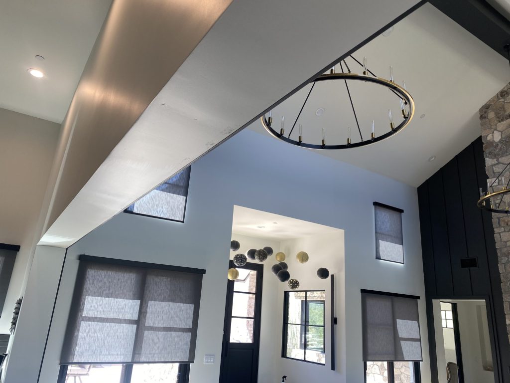
The acoustic volume may include kitchens, hallways, high ceilings, and adjacent zones. Rectangular-room subwoofer recipes become less reliable, and surround positions may conflict with circulation. Define the priority listening area and accept that every seat in an open plan may not receive identical imaging.
Finished-home retrofit
Inspect accessible framing, attic and chase routes, electrical power, cabinetry, equipment locations, and repair options. A hybrid wired/wireless plan may be appropriate, but it should be selected after route investigation—not assumed from the start.
Hard surfaces such as tile, stone, glass, and large painted planes can create strong reflections when they are present; fabric, seating, rugs, and engineered treatments change the result. Those are room-material facts, not climate claims. Likewise, equipment cooling should follow the selected manufacturer’s clearance and ventilation requirements rather than one universal “Arizona” temperature limit.
For a broader room-feasibility exercise that includes display and seating relationships, use the interactive Home Theater Room Planner. The Phoenix home theater and private cinema service page owns complete project design and installation.
Surround sound planning checklist
- Define the experience. Is this a focused cinema, family room, gaming room, music space, or one room doing several jobs?
- Map the listening area. Record the priority seats, row widths, ear heights, walkways, and acceptable compromises.
- Fix the screen axis. Coordinate image size, sightlines, center-channel placement, and front speaker locations.
- Choose a viable channel layout. Confirm that each ear-level and height channel has a distinct, format-appropriate position.
- Plan low frequencies separately. Reserve candidate subwoofer locations, power, signal paths, processing, and access for measurement.
- Coordinate wiring before finishes. Home-run speaker cable where appropriate, provide conduit for likely upgrades, label both ends, protect service loops, and keep low-voltage work within applicable practices.
- Specify electronics from the layout. Count required processed and amplified channels, verify format support, bass management, subwoofer outputs, control integration, and cooling.
- Design the room response. Identify likely reflection, decay, rattle, noise, and isolation issues without confusing treatment with soundproofing.
- Commission and document. Measure multiple seats, save settings, label the rack, record cable routes, train the owner, and define when recalibration is needed.
When professional design and calibration matter most
Professional involvement becomes more valuable as the room and performance target become less forgiving. Consider it early when the project includes four or more height channels, multiple seating rows, more than one subwoofer, an acoustically transparent screen, invisible or architectural speakers, a processor with advanced bass control, significant acoustic treatment, complex retrofit routes, or coordination with an architect, builder, electrician, millworker, lighting designer, or HVAC contractor.
The highest-value work happens before the speakers are purchased. A design package can define the reference seating area, channel layout, coordinates, coverage, cable schedule, conduit, equipment-room needs, amplifier and processor capability, subwoofer strategy, acoustic approach, and commissioning standard. That prevents a common failure: buying an impressive equipment list and discovering that the room cannot place it correctly.
After installation, recalibration is appropriate when speakers or subwoofers move, seating changes materially, crossovers or processing change, acoustic treatments or major furnishings are added, equipment is replaced, or a fault suggests that the saved system state no longer matches the room.
Authoritative planning sources
The technical claims in this guide were checked on September 1, 2026 against current or foundational primary sources. Product features and software behavior can change, so the exact manuals for the selected system still control the final design.
- Dolby Professional: x.y.z layout notation and the LFE-channel distinction
- Dolby: surround-sound speaker setup guides
- Dolby Atmos Home Theater Installation Guidelines
- CEDIA/CTA-RP22 Immersive Audio Design Recommended Practice
- Harman: Subwoofers—Optimum Number and Locations
- CEDIA: smart-home wiring guide
- Dirac: room correction and bass-control overview
Frequently asked questions about surround sound systems
What is the difference between 5.1 and 7.1 surround sound?
A 5.1 system has five ear-level channels—left, center, right and one pair of surrounds—plus one LFE channel. A 7.1 system adds a separate pair of rear surrounds, creating side and rear surround channels. It does not add overhead channels; those appear as the third digit in layouts such as 5.1.4 or 7.1.4.
What does 5.1.4 mean in a Dolby Atmos setup?
It means five ear-level channels, one dedicated LFE channel and four height channels. The height channels are commonly arranged as a front pair and rear pair above the listening area, using in-ceiling, on-ceiling or suitable Dolby Atmos-enabled speakers according to the room and Dolby guidance.
Does “.1” mean I can use only one subwoofer?
No. In technical x.y.z notation, “.1” identifies the LFE channel, not a universal limit of one physical cabinet. One or more subwoofers may reproduce that channel, and they may also handle bass redirected from other speakers. Multiple subs need appropriate placement, processing and calibration.
Is a fully wireless surround sound system really wire-free?
Usually not. Wireless may remove the speaker-signal cable, but active speakers commonly need AC power and a compatible radio or network connection. Battery-powered exceptions exist, and every product has specific compatibility, charging, interference and software requirements. A complete design should document both signal and power paths.
Can room correction fix poor speaker placement?
Room correction can improve measured level, delay, frequency response and bass integration within the system’s capabilities, but it cannot move a speaker, create missing separation, eliminate every deep cancellation, repair a rattle or replace appropriate acoustic treatment. Correct the physical layout first, then measure and calibrate.
What is the difference between acoustic treatment and soundproofing?
Acoustic treatment manages sound behavior inside the room, including reflections, decay and bass response. Soundproofing or sound isolation reduces sound transmission between rooms through construction. They solve different problems, and electronic room correction is a third tool that adjusts the playback system from measurements.
When should speaker wiring be planned in an Arizona home?
Plan it before framing and drywall whenever possible, after the screen and reference seating area establish speaker locations. Specify home runs, conduit, labels, service loops, equipment location and likely future channels. In a finished home, inspect realistic low-voltage routes and repair options before choosing a wireless compromise.
When is professional surround sound calibration worth it?
It is especially valuable for multiple seating rows, more than one subwoofer, immersive height layouts, architectural speakers, advanced processors, acoustic treatment or rooms with difficult geometry. Professional calibration also documents the commissioned state and provides a reliable baseline after future room or equipment changes.
For shorter answers about layouts, Atmos, speakers, acoustics, processors, and private cinema design, visit the home theater and private cinema FAQ library.
Design the room before choosing the channel count
Camelback Smart Homes can map the listening area, screen axis, speaker and subwoofer locations, wiring, processing, acoustic priorities, and calibration plan for a dedicated theater, media room, open great room, new build, or retrofit.
Schedule a theater audio design and calibration consultation.